
What Is a Small Travel Motor and How Does It Work?
A Small Travel Motor is a compact hydraulic drive that moves tracked machines and small mobile equipment. It combines a hydraulic motor, reduction gears, bearings, and a final drive assembly. Together, these parts convert pressurized oil into controlled rotation at the track or wheel. The result is steady movement, useful torque, and reliable operation in confined spaces.
Its working process is practical but not simplistic. A hydraulic pump sends oil through control valves into the motor. Fluid pressure turns an internal rotor or gerotor set. Reduction gears then lower speed and increase torque before power reaches the sprocket. When the operator changes flow direction, the motor reverses travel. A built-in brake may hold the machine when hydraulic pressure falls. This detail matters on slopes.
Small travel motors appear on mini excavators, compact carriers, drilling equipment, and agricultural machines. Their performance depends on oil cleanliness, correct pressure, load conditions, and proper installation. A motor can look sound while worn gears create noise, heat, or uneven movement. That is where careful inspection becomes essential. In practice, specifications alone rarely tell the whole story. Mounting alignment, hose routing, and operator habits also influence service life. Some designs offer impressive compactness, yet compact parts can be less forgiving during maintenance. This article examines the motor’s structure, operating cycle, selection factors, and common warning signs. It also considers a point that is easy to overlook: the best motor is not always the strongest one. It must match the machine.
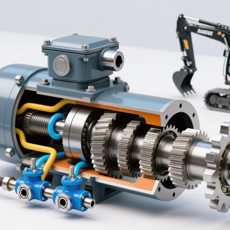
Table of Contents [Hide]
What Is a Small Travel Motor?
A small travel motor is a compact drive unit that moves tracked equipment. It is common in mini excavators, access platforms, and compact carriers. The unit usually combines a hydraulic motor with a planetary gearbox. This design creates strong wheel or track torque without requiring a large housing.
Hydraulic oil enters the motor through control valves. Pressure turns internal gears or pistons. The gearbox then reduces speed and increases torque at the output shaft. That shaft drives a sprocket, which moves the track around its rollers. Direction changes when the valve reverses oil flow. Speed depends mainly on oil flow, while torque depends on pressure and motor displacement.
Size can be misleading. A small travel motor may still handle severe loads. Mud, uneven ground, and repeated starts can produce high stress. During a practical inspection, check for oil leaks, unusual noise, loose mounting bolts, and slow movement. A warm housing is normal, but excessive heat deserves attention. It may indicate restricted flow, worn internal parts, or incorrect oil.
Not every weak track points to motor failure. A damaged valve, blocked filter, or stretched track can cause similar symptoms. This is where diagnosis becomes important. Measure pressure and flow before replacing parts. Small mistakes can become expensive. Manufacturers publish service limits, and technicians should follow those figures rather than rely on guesswork.
What Is a Small Travel Motor and How Does It Work?
| Data Dimension | Typical Data or Range | Description |
|---|---|---|
| Basic Definition | Compact hydraulic drive unit | A small travel motor converts pressurized hydraulic fluid into rotary motion to move tracked equipment, compact carriers, mini excavators, and similar machinery. |
| Primary Energy Source | Hydraulic fluid under pressure | The hydraulic pump supplies pressurized oil through control valves and hoses to the motor. The motor then produces mechanical rotation. |
| Common Motor Type | Orbital, gerotor, radial-piston, or axial-piston | Orbital and gerotor designs are common in compact, low-to-medium-speed applications. Piston designs are often selected when higher pressure, efficiency, or durability is required. |
| Typical Displacement | 10–80 cm³/revolution | Displacement is the theoretical volume of hydraulic fluid required for one shaft revolution. A larger displacement generally produces more torque at the same pressure. |
| Typical Operating Pressure | 140–250 bar continuous; up to about 300–350 bar peak | Actual limits depend on the motor design, hydraulic circuit, fluid condition, temperature, and manufacturer’s specifications. Continuous and peak ratings should not be treated as interchangeable. |
| Typical Speed Range | 20–300 rpm | Travel motors generally operate at relatively low shaft speeds while delivering high torque. Speed depends mainly on hydraulic flow and motor displacement. |
| Typical Flow Range | 5–30 L/min | Hydraulic flow controls rotational speed. For an ideal motor, speed in revolutions per minute is approximately calculated as: flow × 1,000 ÷ displacement. |
| Estimated Output Torque | Approximately 30–600 N·m | Torque varies with displacement, pressure, and mechanical efficiency. A simplified estimate is: torque ≈ pressure × displacement ÷ (2π), before efficiency losses are included. |
| Operating Principle | Pressure differential creates rotation | Fluid entering one port acts on internal gears, pistons, or vanes. The pressure difference generates turning force, and the low-pressure fluid exits through the return port. |
| Directional Control | Two hydraulic flow directions | Reversing the inlet and outlet flow reverses shaft rotation. A directional control valve is commonly used to select forward, reverse, and neutral operation. |
| Speed Control Method | Flow-control valve or variable pump | Reducing flow normally reduces motor speed, while increasing flow raises speed until the motor’s rated limit is reached. Excessive restriction can generate heat. |
| Torque Control Method | System pressure and displacement | Torque rises with hydraulic pressure and motor displacement. A relief valve is used to limit system pressure and protect the motor and other components. |
| Typical Efficiency | Overall efficiency commonly about 70–90% | Volumetric, mechanical, and hydraulic losses reduce the theoretical output. Efficiency changes with load, speed, pressure, temperature, and fluid cleanliness. |
| Common Drive Arrangement | Motor with reduction gearbox | A planetary or spur reduction stage may be added to reduce output speed and increase wheel or sprocket torque for tracked travel systems. |
| Main Components | Housing, rotating element, shaft, bearings, seals, ports, and valve parts | The internal components depend on the motor type. Travel assemblies may also include a brake, reduction gear, pressure-relief valves, and a two-speed mechanism. |
| Hydraulic Fluid Requirement | Clean anti-wear hydraulic oil of the specified viscosity | Fluid grade and viscosity must match the operating temperature and motor requirements. Contamination can accelerate wear, damage seals, and reduce efficiency. |
| Heat Generation | Increases with leakage, restriction, and overload | Hydraulic losses are converted into heat. Correct sizing, adequate cooling, clean fluid, and properly adjusted relief valves help control operating temperature. |
| Common Protection Features | Relief valve, anti-cavitation valve, and mechanical brake | Relief valves limit pressure, anti-cavitation valves protect against low-pressure conditions, and brakes help hold equipment stationary when hydraulic flow is removed. |
| Key Sizing Factors | Machine weight, slope, travel speed, traction, pressure, and available flow | A suitable motor must provide enough starting torque and continuous torque without exceeding pressure, speed, flow, thermal, or structural limits. |
| Typical Applications | Mini excavators, compact tracked loaders, track carriers, agricultural equipment, and small material-handling machines | These applications use hydraulic travel motors where compact size, reversible motion, controllable speed, and high low-speed torque are important. |
| Maintenance Priorities | Fluid cleanliness, leak inspection, seal condition, temperature, and mounting alignment | Regular inspection helps identify damaged hoses, abnormal noise, overheating, external leakage, and reduced travel performance before major component damage occurs. |
Note: The figures shown are representative engineering ranges for small hydraulic travel motors rather than specifications for a particular unit. Always verify pressure, flow, speed, torque, fluid, and mounting requirements against the selected motor’s technical documentation.